Looking for something else?
Titan – Titan Scripts
The MTX-Router-Titan II, MTX-Router-Titan and MTX-Router-Titan mini devices, from firmware version 1.06 onwards, allow the “Titan Scripts” to be edited. The “Titan Scripts” allow we to configure the device easily under given conditions. At the moment, the “Titan Scripts” are orientated to applications with Modbus devices.
For example, we can create a script so that whenever a Modbus register in device A has a specific value, the Titan writes a different value in a Modbus register in device B. Or, we can send an SMS; change a relay, etc. when a Modbus register in device A has a specific value.
The “Titan Scripts”, given they are editable by the user, allow we to create an infinite number of different applications with little effort. Below we have a guide showing the syntax of the “Titan Scripts” along with the available commands; however, the best way to learn how to use them and to see their potential is by understanding the examples.
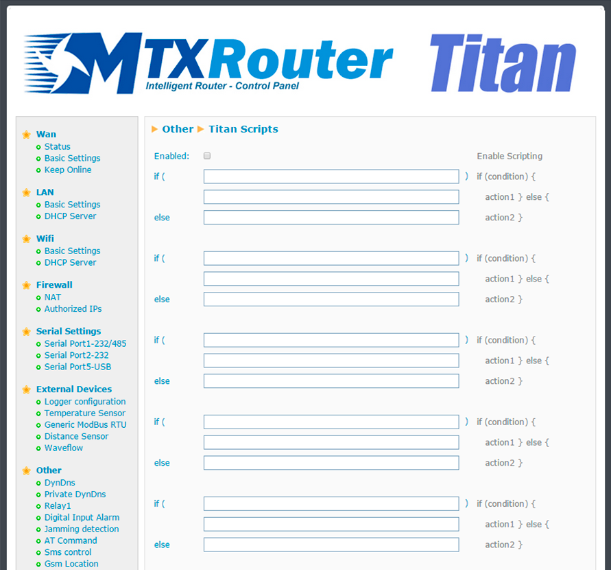
Structure of the “Titan Scripts”
The Titan routers allow we to input up to 10 different scripts. The 10 possible scripts have the same structure, each with three text boxes, as shown below:
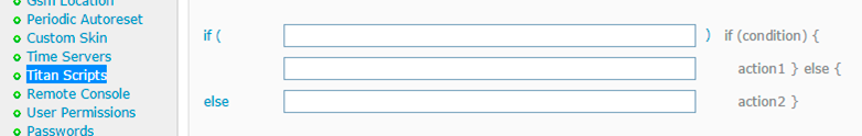
The first text box (IF) indicates the condition; that is, the Titan device will evaluate the logical expression contained here. The second text box (action1) is the action to be executed when the IF condition is true. The third text box (action2) is the action to be carried out when the IF condition is false. In pseudocode:
If what the first text box says is true
Execute the action in the second text box
If what the first text box is not true
Execute the action in the third text box
Even though we still do not know the commands available, let’s see an example:
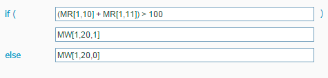
This example will be interpreted as follows:
If the sum of [register 10 of the Modbus device with the address 1] and [register 11 of the
Modbus device with address 1] is greater than 100
Write [the value “1” in register 20 of the Modbus device with address 1]
If the sum of [register 10 of the Modbus device with the address 1] and [register 11 of the
Modbus device with address 1] is not greater than 100
Write [the value “0” in register 20 of the Modbus device with address 1]
Commands Supported by the “Titan Scripts”
Below we can see the commands currently supported, showing what we can do with them. The best way to understand the workings of each of them is by reading the examples in this section of the manual.
“Modbus Read” command:
- Syntax: MR[modbusAddress,modbusRegister]
- Description: reads a Modbus RTU device register. Can be used on the IF field, or the ACTION1 or ACTION2 fields
- Parameters:
- modbusAddress: modbus device address
- modbusRegister: address of Modbus register to be read
- Examples:
- MR[1,10]: reads register 10 of the Modbus device with address 1
- MR[192.168.1.20:502,10]: reads register 10 of the Modbus TCP device with IP address 192.168.1.20 and TCP port 502
“Modbus Write” command
- Syntax: MW[modbusAddress, modbusRegister,registerValue,commandWrite]
- Description: reads a Modbus RTU device register. It can be used on the ACTION1 and ACTION2 fields
- Parameters:
- modbusAddress: modbus device address
- modbusRegister: address of the Modbus device register to be written
- registerValue: value to be written in the register
- commandWrite: OPTIONAL PARAMETER. The Modbus writing commands 3 or 4 can be used. If not indicated, the Modbus command 3 will be used
- Examples:
- MW[1,10,100]: writes the value “100” in register 10 of the Modbus device with address 1, using the Modbus writing command 3
- MW[1,10,100,4]: writes the value “100” in register 10 of the Modbus device with address 1, using the Modbus writing command 4
- MW[192.168.1.20:502,10,100]: writes the value “100” in reegister 10 of the Modbus TCP device with IP address 192.168.1.20 and TCP port 502 using the Modbus writing command 3
- MW[1,10,100,4]: writes the value “100” in reegister 10 of the Modbus TCP device with IP address 192.168.1.20 and TCP port 502 using the Modbus writing command 4
“SET RELAY” command
- Syntax: SR[idRelay, relayValue]
- Description: activates or deactivates an internal relay of the Titan device. Can be used on the fields ACTION1 and ACTION2
- Parameters:
- idRelay: possible values: 1 (Relay 1), 2 (Relay 2)
- relayValue: possible values: 0 (relay not activated), 1 (relay activated)
- Examples:
- SR[1,1]: Activates relay 1 of the Titan device
- SR[2,0]: Deactivates relay 2 of the Titan device
“SEND SMS” command
- Syntax: SS[telephoneNumber, message]
- Description: sends an SNS to a specific telephone number
- Parameters:
- telephoneNumber: Telephone number where the SMS is to be sent to
- message: message to be sent
- Example:
- SS[666123456,Alarm activated] Sends an SMS to the number 666123455 with the text “Alarm activated”
“PAUSE” command
- Syntax: PA[seconds]
- Description: makes a pause in the management of the Titan scripts
- Parameters:
- seconds: length (in seconds) of the pause
- Example:
- PA[5]: Creates a 5 second pause
Comando “DATE”
- Syntax: DA[]
- Description: pauses the Titan script management process
- Parameters:
- Example:
- SS[666123456,Alarm activated DA[] ]: Sends an SMS to the cell 666123456 with the text “Alarm activated + date/time”
- Generates a 5 second pause
Syntax of the “Titan Scripts”
The “Titan Scripts” syntax is very similar to that of Java. In each condition’s “IF” field, we must specify a sentence that has a result of TRUE or FALSE, so that ACTION1 is executed if the IF condition is TRUE, and ACTION2 is executed if the IF condition is FALSE.
In the IF field, we can use all the standard operators in Java to create the condition:
- &&: AND logic condition
- ||: OR logic condition
- + – * /: add, subtract, multiply, divide operators
- ==: “equal to” condition
- >= “more than” condition
- <: “less than” condition
- >=: “more than or equal to” condition
- <=: “less than or equal to” condition
- (): parenthesis to encompass expressions
In the ACTION1 and ACTION2 field, we must use the MW, SR, SS action commands, although we can also use MR for more flexibility (this will become clearer in the examples that will come later). We can also use the operator && if we want ACTION1 and ACTION2 to carry out several actions. For example, we can make ACTION1 carry out two actions: write a Modbus register and send an SMS.
- &&: concatenation of ACTION commands
Action Commands Execution Mode
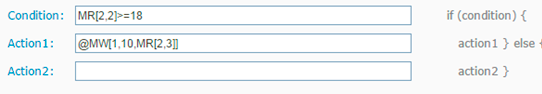
Action fields have different execution modes. Edge mode (default), continuous (@) or only in the event of changes (#). The following examples show how this works.
- Edge execution (default mode):
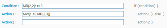
In this case the action MW[1,10,MR[2,3]] is executed just once upon the condition MR[2,2]>=18; i.e. once Action1 has been executed, it will not be executed again until the condition MR[2,2]>=18 is false, and then when the condition is true. This is useful when the user wants to send SMS message alerts or email alerts as this avoids continuous repeated messages.
- Continuous execution (@):
In this case the action MW[1,10,MR[2,3]] is executed whenever the condition MR[2,2]>=18 is true. Do NOT use this option if SMS or emails will be sent as this will result in continuous messages being sent.
- Execution upon changes (#):
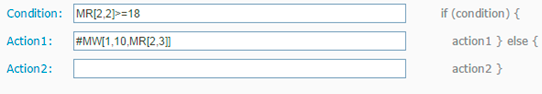
In this case the action MW[1,10,MR[2,3]] is executed whenever there is a change in the action to be executed with respect to the the last execution. Therefore, for this example, it will be executed every time there is a change in the value MR[2,3].
Examples of “Titan Scripts”
The best way to understand how “Titan Scripts” work is by looking at examples. Below we can see a selection of examples to assist we.
EXAMPLE 1
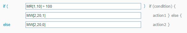
If [register 10 of the Modbus device with the address 1] is greater than 100
Write [the value “1” in register 20 of the Modbus device with address 2]
Otherwise
Write [the value “0” in register 20 of the Modbus device with address 2]
EXAMPLE 2
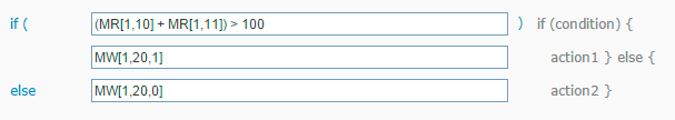
If [register 10 of the Modbus device with the address 1] plus [register 11 of the Modbus device with address 1] is greater than 100
Write [the value “1” in register 20 of the Modbus device with address 1]
Otherwise
Write [the value “0” in register 20 of the Modbus device with address 1]
EXAMPLE 3
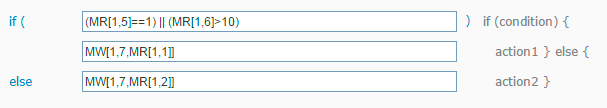
If [register 5 of the Modbus device with the address 1 has the value “1”] OR [register 6 of the Modbus device with address 1] is greater than 10
Write [in register 7 of the Modbus device with address 1 the current value of register 1 in the Modbus device with address 1]
Otherwise
Write [in register 7 of the Modbus device with address 1 the current value of register 2 in the Modbus device with address 1]
EXAMPLE 4
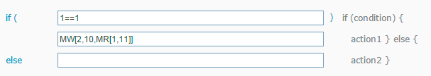
Always (since the condition 1==1 will always be true)
Write [in register 10 of the Modbus device with address 2 [the current value of register 11 of the Modbus device with address 1]
EXAMPLE 5
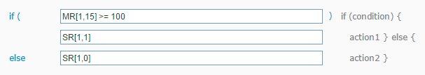
If [register 15 of the Modbus device with address 1] is greater than or equal to 100
Activate Titan device’s Relay 1
Otherwise
Deactivate Relay 1 on the Titan device
EXAMPLE 6
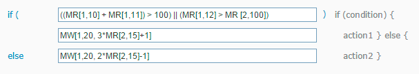
If (( [register 10 of the Modbus device with address 1] + [register 11 of the Modbus device with address 1]) is greater than 100) OR if (( [register 12 of the Modbus device with address 1] is greater than [register 100 of the Modbus device with address 2])
Write [in register 20 of the Modbus device with address 1 [the current value of register 15 of the Modbus device with address 2 multiplied by 3 plus 1]]
Otherwise
Write [in register 20 of the Modbus device with address 1 [the current value of register 15 of the Modbus device with address 2 multiplied by 2 subtract 1]]
EXAMPLE 7
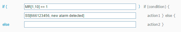
If [register 10 of the Modbus device with address 1] is equal to 1
Send an SMS with the text “new alarm detected” to the telephone number 666123456
EXAMPLE 8
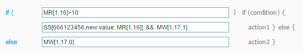
If [register 16 of the Modbus device with address 1] is greater than 10
Send an SMS with the text “new value: [value read from register 16 del of the Modbus device with address 1]” to the telephone number 666123456 AND AFTER Write [in register 17 of the Modbus device with address 1 the value 1]]
Otherwise
Write [in register 17 of the Modbus device with address 1 the value 0]]
EXAMPLE 9
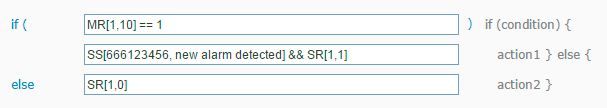
If [register 10 of the Modbus device with address 1] is equal to 1
Send an SMS with the text “new alarm detected” to the telephone number 666123456 AND AFTER Activate the Titan device’s internal Relay 1
Otherwise
Deactivate the Titan device’s internal Relay 1
EXAMPLE 10

If [register 15 of the Modbus device with address 1] is greater than 10
[Activate the Titan device’s internal Relay 1] AND AFTER [pause for 5 seconds] AND AFTER [Deactivate the Titan device’s internal Relay 1]
EXAMPLE 11
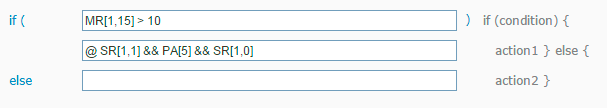
If [register 15 of the Modbus device with address 1] is greater than 10
CONTINUOUSLY [Activate the Titan device’s internal Relay 1] AND AFTER [pause for 5 seconds] AND AFTER [Deactivate the Titan device’s Relay 1]
The difference between example 10 and 11 lies in the @ symbol. This indicates that the action is continuously executed. This means that in example 10, ACTION1 is executed just once when the IF condition is true, and will not be executed again until ACTION1 changes or ACTION2 is executed. In example 11 however, ACTION1 is executed continuously whenever the IF condition is true; i.e. the relay is changing all the time.
EXAMPLE 12
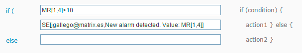
If [register 4 in Modbus device with address 1] is greater than 10
Send an email with the text “New alarm detected. Value [value read from register 4 of the Modbus device with address 1]” to the email jgallego@matrix.es
ADDITIONAL NOTES
- Remember that if the command SE[] is used to send emails, the device must be configured beforehand using the menu “Other > Email configuration”


 Enter the “ethernet” or “modem” connection type:
 For an ethernet configuration, make sure the IP parameters are compatible with server access according to the concentrator local network configuration. For an ethernet connection, the configuration must be compatible with the concentrator’s local network topology so that it can access the servers. This configuration is done from the “Networks” configuration page (see section 3.2.2.3: “Networks”).
For a modem connection, the modem configuration must be correct before a connection can be set up. This configuration is done from the “Modem” configuration page (see section 3.2.2.4: “Modem”).
The parameters for the servers to be configured are at least the following:
For an ethernet configuration, make sure the IP parameters are compatible with server access according to the concentrator local network configuration. For an ethernet connection, the configuration must be compatible with the concentrator’s local network topology so that it can access the servers. This configuration is done from the “Networks” configuration page (see section 3.2.2.3: “Networks”).
For a modem connection, the modem configuration must be correct before a connection can be set up. This configuration is done from the “Modem” configuration page (see section 3.2.2.4: “Modem”).
The parameters for the servers to be configured are at least the following:
 Therefore the following fields need to be configured: “Interface”, “Type”, “Server type”, “Address”, “Port”, “Login” and “Password”.
The other fields can be left at the default values subject to the directories having been properly created beforehand. See section 3.1.2: “Configuration files” for more details.
Therefore the following fields need to be configured: “Interface”, “Type”, “Server type”, “Address”, “Port”, “Login” and “Password”.
The other fields can be left at the default values subject to the directories having been properly created beforehand. See section 3.1.2: “Configuration files” for more details.


 Wait. The concentrator will reboot using its factory configuration.


