Titan – Configuration: WAN

Looking for something else?

Titan – Configuration: WAN

The WAN section refers to everything related to the 2G/3G route configuration, from the connection status, network configuration parameters and supervision of the connection.

WAN: Status

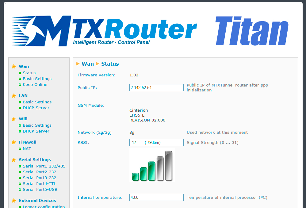
This screen shows the general status of the router:

  • Public IP: WAN IP address (address of the GPRS/3G connection) if available
  • GSM Module: indicates the manufacturer and the router’s internal GSM module model
  • Network (2G/3G): indicates if the current WAN connection is using 2G (GPRS) or 3G
  • RSSI: indicates the signal strength. 0=none, 31=maximum
  • Internal Temperature: shows the internal processor’s temperature (it does not indicate the outside temperature. To find this out, a Temperature Sensor peripheral device can be connected to the router)

Titan-Manual - WAN Status

WAN: Basic Settings

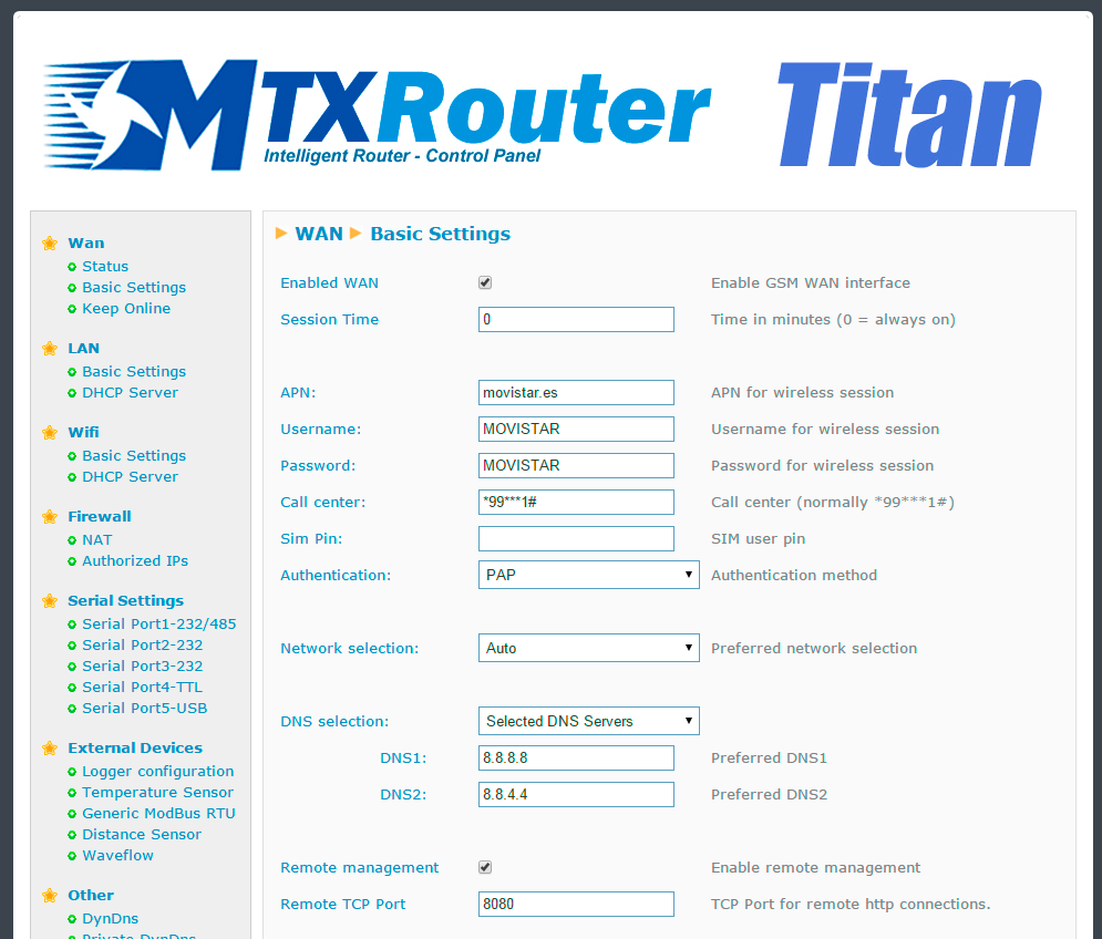
This section assists with the configuration of the WAN (2G/3G) connection parameters. We will need to know certain information about the SIM card such as the APN, login and password. Our network provider should provide we with these.

  • Enabled WAN: select this to allow the MTX-Router-Titan to activate the 2G/3G device.
  • Session Time: indicates the time in minutes that the 2G/3G connection should be active. If the value is “0”, it means that the connection is active all the time. If a value greater than 0 is specified, the number specifies the number of minutes during which the connection will be active following an event such as an SMS message being received or a missed call. Go to the configuration “Other > SMS Control” to activate and configure these events for when a number greater than 0 is specified.
  • APN: operator APN. Consult our GSM provider for this.
  • Username: operator Username. Consult our GSM provider for this
  • Password: operator Password. Consult our GSM provider for this.
  • Call center: call center number. Usually *99***1#
  • SIM pin: if our SIM card has a PIN number, it should be specified here.
  • Authentication: the method of authentication. Usually PAP
  • Network selection:
    • auto: the router will use 3G when 3G coverage is available, and 2G in the event that there is no 3G coverage
    • 3G: the router will use 3G networks in every case. If there is no 3G coverage, it will not change to 2G
    • GPRS: the router will use 2G networks in all cases
  • DNS1 and DNS2: DNS servers for domain name resolution. It is recommended that those belonging to Google (8.8.8.8 and 4.4.4.4) are used, or whatever our provider gives we
  • Remote management: if activated, we will be able to access the router’s web configuration remotely via the public IP address (indicated in WAN>Status)
  • Remote TCP Port: indicates the TCP port for remote configuration. For example, if the value is 8080, the URL of the configuration will be http://x.x.x.x:8080. The standard default port is 80, but if we wish to use NAT to the TCP80 port in an ETH device (IP camera, PLC), we will need to change it, for example, to 8080

Titan-Manual - WAN Basic Settings

ADDITIONAL NOTES

  • Once the configuration is finished, click “SAVE CONFIG” to save the changes. Remember that the router should be restarted for the changes to take effect.

WAN: Basic Settings, Utilities

The utilities that we can find at the bottom of the “WAN > Basic Settings” screen allow we to select the main and secondary GSM operators when using a Global SIM card. (A Global SIM card allows we to connect to several network operators that are available. For example, in Spain, we would be able to connect to Movistar, Vodafone or Orange).

  • Strong scanning: scans the GSM stations for all available network operators. This action uses a significant amount of processing poour and therefore can take up to 4 minutes. On occasion, it may be necessary to try the process again. If successful, a list of the detected BTS will be shown, indicating the operator’s name, its code, its availability and the type of network (2G/3G). This could be very useful in helping we decide the best operator to use in a particular place.

Titan User Manual - WAN Basic Settings Utils

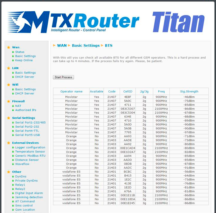
With Strong Scanning, 3G connectivity is lost during the process and therefore we recommend using the Ethernet interface to carry this out. Because of this, “Strong Scanning” has two buttons – “start process from Ethernet” and “Start process from 3G”.

If the process is carried out using Ethernet, press this button and the results will be shown on screen once finished.

If the process is carried out using 3G, press this button and after five minutes, the device will reset itself. We will have to return to the screen manually and press the “See last results” button in order to see the results.

  • Light scanning: this carries out a similar process, but only those operators that are available for our SIM card are identified. 3G connectivity is not lost during the process, which could last up to 2 minutes, meaning that it is ideal when carried out remotely via 3G.
  • Choose operators: this allows we to choose the GSM operator and the secondary operators. It can only be used when a Global SIM (allowing connections to several operators) is inserted. The default setting is “Automatic”.

Titan User Manual - WAN Global SIM

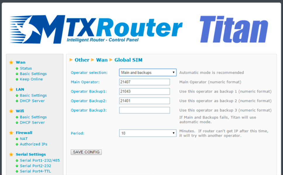
Example contained in the screenshot above. We choose the “Main and Backups” option, which forces the indicated GSM operators to be used. The main operator is 21407 (Movistar). If an IP address is not obtained using this network, the process is retried using operator 21043 (Orange), and if this fails, it tries again with operator 21401 (Vodafone). If the third network operator also fails, the router will try to connect to a GSM network automatically.

If we select the “Automatic” option instead of “Main and Backups”, the router will try to select the operator in the order that is stablished in the SIM card’s internal tables. Except for in locations prone to connectivity problems, we recommend we use the “Automatic” option.

The section Wan > Basic Settings > Utils is not available for 4G models.

  • Automatic APN: This new feature will work when we enter the text “auto” in the “APN” field. That is, as indicated in the following figure:

Titan User Manual - WAN Basic Settings APN

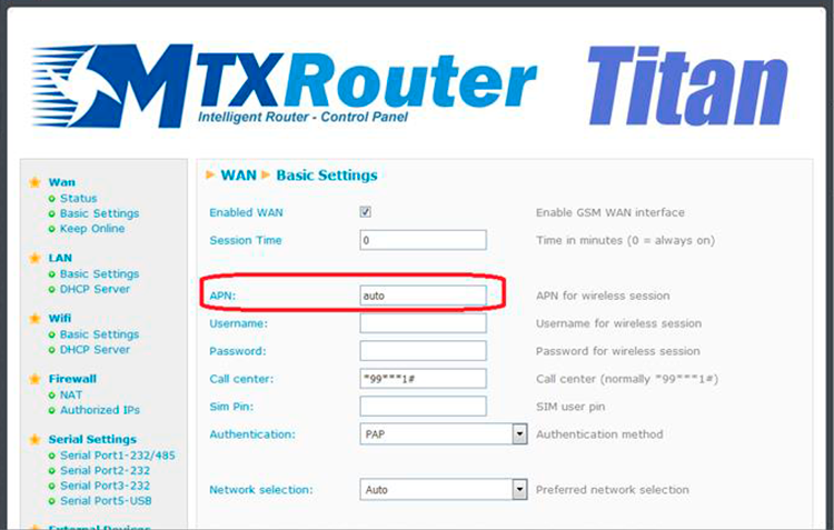
When “auto” is specified in the APN field, the Titan router will not use the APN, Username and Password fields in this section, instead, it will look up in the table (which can be consulted by pressing the “Automatic APN “) The appropriate APN, Username and Passwords. This is particularly useful if we intend to send the router to a third party and only have to insert the SIM without configuring anything else.

Although the list of operators has a considerable number of data (apn, username, password) it is strongly recommended to review the list and update it with the desired operators.

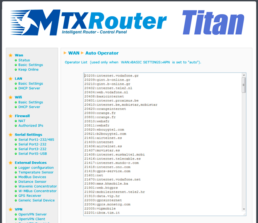
The format of the file is very simple:
codigoSim: apn, username, password

The username and password only need to be indicated in those operators that actually use them, not being necessary otherwise.

Failover: in case we are using the Ethernet interface or the Titan router WiFi as an Internet output and it fails, we can configure this section so the Titan router automatically connects to the Internet via 2G/3G/4G.

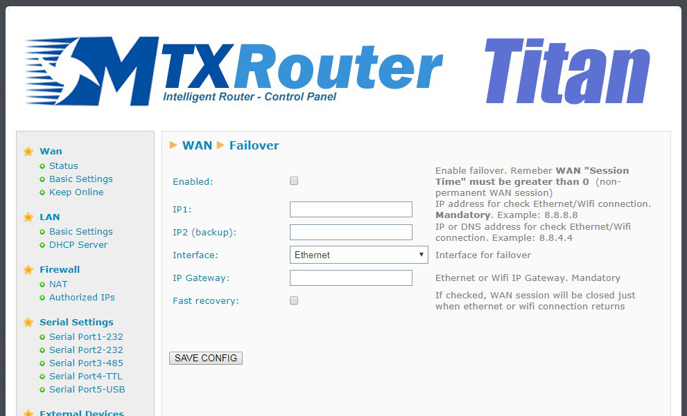
  • Enabled: activate this box to enable the Failover
  • IP1: IP address for the periodic ping by the used interface (Ethernet or WiFi) to make sure the communications are working
  • IP2: backup IP address for the periodic ping by the used interface (Ethernet or WiFi) to make sure the communications are working
  • Interface: specify the interface being used to access the Internet (Ethernet or WiFi)
  • IP gateway: specify the output gateway IP address used for the Ethernet or WiFi connection
  • Fast recovery: select this box in case we want the 2G/3G/4G connection to end when the Ethernet or WiFi connection is restored. Otherwise it will be connected the amount of time specified in WAN > Basic Settings > Session Time

Important: in case we use the Failover feature we need to make sure to enable the box “WAN > Basic Settings > Enabled WAN” and to enter a value > 0 in the field “WAN > Basic Settings > Session Time.” That value will be the minutes the 2G/3G/4G connection will be enabled in case there is a problem with the Ethernet or WiFi interface.
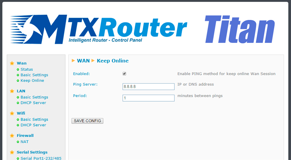
WAN: Keep Online

On this screen we can configure a PING to ensure the router’s connectivity. If the PING fails on three occasions, the 2G/3G connection will be reset. We recommend the use of this characteristic.

  • Enabled: activate to allow the Titan to periodically send a PING to check the connectivity
  • Ping Server: indicates the server’s IP address where the PING should be sent
  • Period: indicates how frequently a PING should be sent

Additional Notes

  • Once the configuration is finished, click “SAVE CONFIG” to save the changes. Remember that
    the router should be restarted for the changes to take effect

Do you have a question? Need a quote? Please contact us.

  • This field is for validation purposes and should be left unchanged.

Appendices and other documents

Annexes et autres documents

Appendices and other documents

Appendices and other documents

Appendices and other documents

Appendices and other documents

Appendices and other documents

Appendices and other documents

Appendices and other documents

FAQ

No, the concentrator is not able to decrypt data from WM-BUS equipment because it does not have a safe on board to guarantee the security of the encryption keys of your equipment. The recovered data is deposited without modification (without decryption) by the concentrator on your remote server.
Please check these items in this order:
  • the battery level: if the battery level is too low or empty, the product will not run properly or not run at all.
  • Modem reception level: a bad signal at the modem may also prevent the hub from uploading files. Look to move the product or install an external antenna to improve signal quality.
  • The last configuration file: a bad configuration file can block the product.

Remotely, by checking the regularly uploaded files if the product configuration is correct.

On site, by passing the magnet over the product, you will hear 3 short beeps.

Replace the product and inject the configuration from the old product into the new one. If a white list is used, remember to inject it into the new product as well.

Appendices and other documents

Other manuals

Application Notes

FAQ

Gateway configuration:

Start by checking that the computer’s IP parameters are compatible with the WebdynSunPM IP address (by default 192.168.1.12)

Launch a web browser (Chrome, Firefox, Edge, Safari, etc.) and enter the WebdynSunPM concentrator IP address in the address bar. An authentication page is displayed:

The default accesses are:

IdentifiantMot de passe
userhighhigh

Click “Login”

There are two configuration solutions, using the web interface and using text messages:
  • Configuration using the web interface:
Start by establishing a connection to the concentrator by connecting to it to access the server configuration: Enter the “ethernet” or “modem” connection type: For an ethernet configuration, make sure the IP parameters are compatible with server access according to the concentrator local network configuration. For an ethernet connection, the configuration must be compatible with the concentrator’s local network topology so that it can access the servers. This configuration is done from the “Networks” configuration page (see section 3.2.2.3: “Networks). For a modem connection, the modem configuration must be correct before a connection can be set up. This configuration is done from the “Modem” configuration page (see section 3.2.2.4: “Modem). The parameters for the servers to be configured are at least the following: Therefore the following fields need to be configured: “Interface”, “Type”, “Server type”, “Address”, “Port”, “Login” and “Password”. The other fields can be left at the default values subject to the directories having been properly created beforehand. See section 3.1.2: “Configuration files for more details.
  • Text message configuration:
Text message configuration requires sending the following commands:
      • Apn: to configure the SIM card APN. (see section 3.2:“apn” modem configuration command)
      • Ftp: to configure the FTP server that will contain the concentration configuration (see section 3.3: “ftp” FTP configuration command”).
      • Connect: to launch the connection to the FTP server and load the configuration (see section 3.1: ““connect” connection command

Access to the FTP server depends on the selected solution.

If you have chosen a portal, it will give you the FTP server access identifiers.

If you want to use your own FTP server, contact your network administrator.

For all other configurations, and to determine the best solution, contact the Webdyn sales department which will advise you and direct you to the relevant contacts: contact@webdyn.com

General gateway use

There are 2 methods to force a concentrator factory reset:
  • Press the Factory Reset button on the concentrator for 20 seconds:
Wait. The concentrator will reboot using its factory configuration.
  • If a SIM card is installed and configured, a “factory” text message can also be used for factory reset. Just send the “factory” text message to the SIM card phone number (see section 3.7: “factory” reset command”)

It is possible to send commands to connected devices if they accept them.

The WebdynSunPM can store up to 50Mb of uncompressed data per declared device.

If there is no access to the remote server, the WebdynSunPM concentrator can store the data for several months.

The maximum data storage time varies depending on the amount of data to be collected and the configured collection frequency.

The average storage time varies from 3 to 4 months.

The average service life of the battery is 5 years.

It may vary depending on the installation environment.

All our products are guaranteed for 2 years.

For more information, read the general terms and conditions of sale.

The data volume depends on the exchanged files.

The average is about 5 MB per month but this varies from one installation to another.

Inverter compatibility

See section 1.4: “Supported devices”.

Modbus device compatibility:

Yes, different Modbus devices can be connected to the same serial port.

Device compatibility:

    • Same type of RS485 or 4 wire connection.
    • All devices should be able to be configured using identical bus specifications. Same speed, same parity, same number of stop bits and data bits on all devices and on the WebdynSunPM.
    • Each device must be assigned a unique Modbus address (between 1 and 247) on the bus. (UnitID)

Appendices and other documents

FAQ

CONFIGURATION OF THE WEBDYNSUN GATEWAY

  • Start by checking that your computer’s IP parameters are compatible with the WebdynSun’s “IP” address (the default is 192.168.1.12). 
  • Next, launch a web browser (Firefox or IE) and enter the WebdynSun’s IP address in the address bar. An authentication page will appear: 

The default accesses are:
Username: userhigh
Password: high

  • Click on “log in”  

There are two types of configuration: via the web interface or via SMS.

Configuration of the web interface:

1/ Go to the configuration page with the gateway IP address (default 192.168.1.12)

2/ Go to the Configuration tab.

3/ Select either the Ethernet or modem connection mode:

If connecting via the local network (Ethernet):

  • Edit the WebdynSun’s IP parameters by assigning it a network-compatible address.

Please note, all fields must be completed in accordance with the configuration of your local network.

If connecting via the GPRS network (Modem):

  • Change the connection settings of the GPRS modem to the settings provided by your mobile operator.

4/ Edit the FTP server parameters.

5/ Confirm the changes.

6/ Restart the WebdynSun gateway using the new settings.

7/ In the menu, click on the “installation” tab, followed by the “connection” sub-tab and start the connection.

Configuration via SMS:

This configuration method requires the use of an active SIM card with a data option and a pin code that must be either “0000” or disabled.
The SIM card must be inserted into the unit before connection to the mains supply.
After connection to the mains supply, send the following SMS messages to the number of the previously inserted SIM card:

SMS for configuring the APN:
After replacing the generic fields with those of your operator, send the following SMS*:
apn=apn_name;usr=user_name;pwd=password;

Replace the above SMS fields with the following information:

  • apn_name: APN name supplied by your mobile operator
  • user_name: APN ID supplied by your mobile operator
  • password: APN password supplied by your mobile operator

SMS for FTP configuration:
After replacing the generic fields with those of your FTP server, send the following SMS*:
Ftp=server_name:user_name:password:port;

Replace the above SMS fields with the following information:

  • server_name: FTP server address
  • user_name: FTP account ID
  • Password: FTP account password
  • Port: FTP server port (the default port is 21)

Connection SMS:

Send the word “connect” by SMS* to launch a connection to the FTP server

*Please note: the formatting of the SMS must be exactly identical to that shown above (e.g.: no spaces between characters, etc.)

There are 2 ways of resetting the gateway.

  • If connecting by Ethernet:
    • Disconnect from the mains
    • Remove the cover
    • Disconnect the battery
    • Put the DIP Switch 2 on the WebdynSun card in “ON” position
    • Start the WebdynSun by connecting it only to the mains power supply
    • Wait until all the LEDs flash and then stop flashing (3 to 5 mins).
    • Disconnect from the mains
    • Reset the Dip Switch 2 to “OFF” 
    • Reconnect the battery
    • Reconnect to the mains supply and the WebdynSun starts normally.
  • If there is a SIM card inserted in the unit:
    • Send an SMS message containing the word “factory” to the number of the inserted SIM card.

NB : Resetting the gateway restores the configuration to its original state. Please note: data will be saved but the specific settings will not. Therefore, all the settings must be reconfigured.

Commands can be sent to connected devices with the exception of certain inverters and Modbus slaves that do not accept write requests.

If the device allows it, command files can be created on the FTP server.

The WebdynSun has a memory of about 100MB.

Therefore, if the remote server cannot be accessed, the WebdynSun gateway can backup data for several months.
The maximum data backup time varies depending on the amount of data to be collected.

The average backup time ranges from 3 to 4 months.

The average battery life is 5 years.

It may vary depending on the installation environment.

Yes, data may be sent to a PLC if the latter is equipped with a Modbus protocol.
The “Report” configuration file allows the WebdynSun gateway to automatically write the values read on a Modbus slave

All our products are guaranteed for 2 years.

For further information, please see our general conditions of sale.

Files uploaded by the WebdynSun gateway are compressed in Gz format.

The data contained in these files is structured in csv format.

The data volume depends on the files exchanged.

The average is about 5 MB per month but this varies from one installation to another.

INVERTER COMPATIBILITY WITH THE WEBDYNSUN GATEWAY

Different brands of inverter may be connected to the RS485(B) port or via the Ethernet port if the inverter protocol is based on the Modbus protocol (RTU or TCP).

However, different brands of inverters cannot be connected to the same RS485(A) port.

For a list of compatible inverters, please see the product page of the WebdynSun data gateway
  • Check if the correct inverter protocol is selected before starting detection:
  • Check the wiring and configuration of the inverters by referring to the inverter appendices.
  • Check that the inverters are not in OFF or stand-by mode.
  • Check that the line end plugs on the RS 485(A) Bus are turned on.

COMPATIBILITY WITH MODBUS DEVICES

Yes, any device you wish to connect must be configured and its Modbus definition file must be created.

The configuration is mainly based on the RS485 serial bus parameters and the IP parameters.

Yes, different Modbus devices can be connected to the same RS485 (B) port.

However, they must have the same communication parameters (bus parameters or compatible IP parameters), in order for them to communicate with each other.

Appendices and other documents

Appendices and other documents

Appendices and other documents

Appendices and other documents

Appendices and other documents

  • Warning – Firmware update V4.07.02 For the old version with SIM CARD of the pin code is 0000 you can update in this version. For the second case : When you insert a SIM CARD with pin code is 0000 used in this version (4.07.02) Downgrading to a previous version is not permitted.

Appendices and other documents

  • Warning – Firmware update V4.07.02 – For the old version with SIM CARD of the pin code is 0000 you can update in this version.

    For the second case : When you insert a SIM CARD with pin code is 0000 used in this version (4.07.02) Downgrading to a previous version is not permitted.

Annexes and other documents

FAQ

Annexes and other documents

FAQ

Annexes and other documents

FAQ

Annexes and other documents

FAQ

CONFIGURATION OF THE WEBDYNRF GATEWAY

  • If the file is deleted from the directory after connecting the WebdynRF gateway, the problem is usually due to a file format error. The configuration and control files must follow the format described in the schema (XSD) files. To check schema consistency, open the XML file with the Notepad++ text editor and install the “XML Tool” add-on. Next, copy the corresponding XSD file to the XML file in the same directory, and select “Validate now” in XML Tool. Errors detected by the tool should be displayed.
  • If the file is not deleted from the server, the most common problem is that the file has not been located correctly. The file must be available on the server in the “INBOX” directory and in the sub-directory bearing the product UID name (e.g.: “/INBOX/0045CE/”).

GENERAL USE OF THE WEBDYNRF GATEWAY

The amount of data exchanged on the GPRS network varies depending on the configuration. However, the average consumption would be about 5MB / month.
The WebdynRF gateway consumes an average of about 250mA.

There are 2 firmware updating methods:
Local updating:
On the WebdynRF configuration interface, go to the “Actions” tab and select the updater in the “File upload” menu before clicking on the “Upload” button

Remote updating:
Upload the file containing the updater (file with extension “.bz2”) in the “BIN” directory to the FTP server . Next, place the update command in the INBOX directory corresponding to your gateway (“INBOX/”, with, the identifier of the gateway concerned)

The update command must follow the following format:

      updater.tar.bz2
      checksum_md5

updater.tar.bz2
checksum_md5

With:

  • updater.tar.bz2: Updater file name uploaded to the “BIN” directory
  • checksum_md5: Md5 code of the updater file

A lack of connection to the FTP server may be due to a network connection problem (Ethernet or GPRS), an FTP login problem or a failure to initiate the connection.

If you cannot connect to the network, check the following points:

  • Ethernet:
    • Modem set to “off” or “always off”
    • “Gateway” fields correctly entered
    • At least one DNS server must be configured
  • GPRS:
    • Modem set to “on”
    • APN, APN ID and APN password correctly entered
    • GPRS call number set to “*99***1#”

If you cannot log in, check the following points:

  • Incorrect FTP parameters
  • TCP port 21 closed at output
  • Domain name resolution problem: the DNS server is not specified

If the connection fails to initiate:

In this case, only the automatic connection does not work. The problem is probably caused by an incorrect schedule configuration. Please note, the schedule ID must be an integer.

 PARTICULAR APPLICATION OF THE WEBDYNRF WIRELESS M-BUS GATEWAY

For the WM-bus module data to be transmitted, you must:

  • Choose the mode corresponding to the modules used (S, T or N)
  • Define the modules or groups of modules to be processed

A module may be defined in a unique way by all the fields below:

  • Id
  • Manufacturer
  • Version
  • Medium

If a module’s data is encrypted, the encryption key for this module can be defined in the “Key” field.

To simplify the entry of the modules to be processed, a module group can be defined that conforms to the fields entered. The other fields will then be left empty (below is an example of a configuration for retrieving all Webdyn manufacturer (WDN) modules with the encryption key “00000000000000000000000000000000”.

  •   Id :
  •   Manufacturer : WDN
  •   Medium :
  •   Version :
  •   Label : Webdyn
  •   Key : 00000000000000000000000000000000

Note: In order for the modules (filters) entered to be taken into account, the “ByPass filter” mode must be deactivated.

Click here to read the media file 

Click here to read the units file 

 PARTICULAR APPLICATION OF THE WEBDYNRF WAVENIS

The tool is connected to the gateway via the installer access (install).

It is therefore necessary to use the installer password (default is “middle”), and not the administrator’s password (default is “high”)

The statuses transmitted by the WebdynRF gateway are the raw values contained in the Wavenis modules. They are transmitted without interpretation. For further details, please refer to the Coronis module manuals.

Appendix and other documents

FAQ

CONFIGURATION OF THE WEBDYNRF GATEWAY

  • If the file is deleted from the directory after connecting the WebdynRF gateway, the problem is usually due to a file format error. The configuration and control files must follow the format described in the schema (XSD) files. To check schema consistency, open the XML file with the Notepad++ text editor and install the “XML Tool” add-on. Next, copy the corresponding XSD file to the XML file in the same directory, and select “Validate now” in XML Tool. Errors detected by the tool should be displayed.
  • If the file is not deleted from the server, the most common problem is that the file has not been located correctly. The file must be available on the server in the “INBOX” directory and in the sub-directory bearing the product UID name (e.g.: “/INBOX/0045CE/”).

GENERAL USE OF THE WEBDYNRF GATEWAY

The amount of data exchanged on the GPRS network varies depending on the configuration. However, the average consumption would be about 5MB / month.
The WebdynRF gateway consumes an average of about 250mA.

There are 2 firmware updating methods:
Local updating:
On the WebdynRF configuration interface, go to the “Actions” tab and select the updater in the “File upload” menu before clicking on the “Upload” button

Remote updating:
Upload the file containing the updater (file with extension “.bz2”) in the “BIN” directory to the FTP server . Next, place the update command in the INBOX directory corresponding to your gateway (“INBOX/”, with, the identifier of the gateway concerned)

The update command must follow the following format:

      updater.tar.bz2
      checksum_md5

updater.tar.bz2
checksum_md5

With:

  • updater.tar.bz2: Updater file name uploaded to the “BIN” directory
  • checksum_md5: Md5 code of the updater file

A lack of connection to the FTP server may be due to a network connection problem (Ethernet or GPRS), an FTP login problem or a failure to initiate the connection.

If you cannot connect to the network, check the following points:

  • Ethernet:
    • Modem set to “off” or “always off”
    • “Gateway” fields correctly entered
    • At least one DNS server must be configured
  • GPRS:
    • Modem set to “on”
    • APN, APN ID and APN password correctly entered
    • GPRS call number set to “*99***1#”

If you cannot log in, check the following points:

  • Incorrect FTP parameters
  • TCP port 21 closed at output
  • Domain name resolution problem: the DNS server is not specified

If the connection fails to initiate:

In this case, only the automatic connection does not work. The problem is probably caused by an incorrect schedule configuration. Please note, the schedule ID must be an integer.

 PARTICULAR APPLICATION OF THE WEBDYNRF WIRELESS M-BUS GATEWAY

For the WM-bus module data to be transmitted, you must:

  • Choose the mode corresponding to the modules used (S, T or N)
  • Define the modules or groups of modules to be processed

A module may be defined in a unique way by all the fields below:

  • Id
  • Manufacturer
  • Version
  • Medium

If a module’s data is encrypted, the encryption key for this module can be defined in the “Key” field.

To simplify the entry of the modules to be processed, a module group can be defined that conforms to the fields entered. The other fields will then be left empty (below is an example of a configuration for retrieving all Webdyn manufacturer (WDN) modules with the encryption key “00000000000000000000000000000000”.

  •   Id :
  •   Manufacturer : WDN
  •   Medium :
  •   Version :
  •   Label : Webdyn
  •   Key : 00000000000000000000000000000000

Note: In order for the modules (filters) entered to be taken into account, the “ByPass filter” mode must be deactivated.

Click here to read the media file 

Click here to read the units file 

 PARTICULAR APPLICATION OF THE WEBDYNRF WAVENIS

The tool is connected to the gateway via the installer access (install).

It is therefore necessary to use the installer password (default is “middle”), and not the administrator’s password (default is “high”)

The statuses transmitted by the WebdynRF gateway are the raw values contained in the Wavenis modules. They are transmitted without interpretation. For further details, please refer to the Coronis module manuals.

Annexes et autres documents

  • WARNING :  Pour les anciens produits qui disposent d’une carte SIM avec un code PIN à 0000 , la mise à jour vers la version 4.07.02 sera fonctionelle.

    Second cas : Si la carte SIM avec un code PIN à 0000 est utilisée dans cette version (4.07.02), le passage vers une mise à jour antérieure est interdit.